Addisim project looks at the design of 3D printed plastic components
The aim of the completed AddiSim 21105 N project (8347) was to derive a simplified method for the structural simulation of SLS-manufactured plastic components based on mechanical investigations. By means of the developed procedure, comprehensive results on the behavior of the printed material are obtained on the basis of a detailed measurement of the print space. The method generated at the Fraunhofer LBF includes important findings for dimensioning SLS-manufactured components in a light-weight and reliable manner. Manufacturers of printed components often do not have fully equipped mechanical test laboratories at their disposal. Nevertheless, they are expected to provide a lightweight design. Here, the Fraunhofer LBF offers support based on the test results obtained and the simplified design methodology .
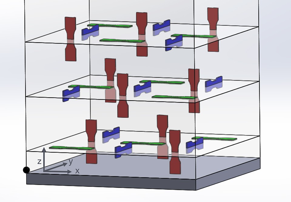
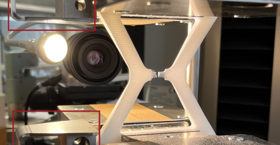
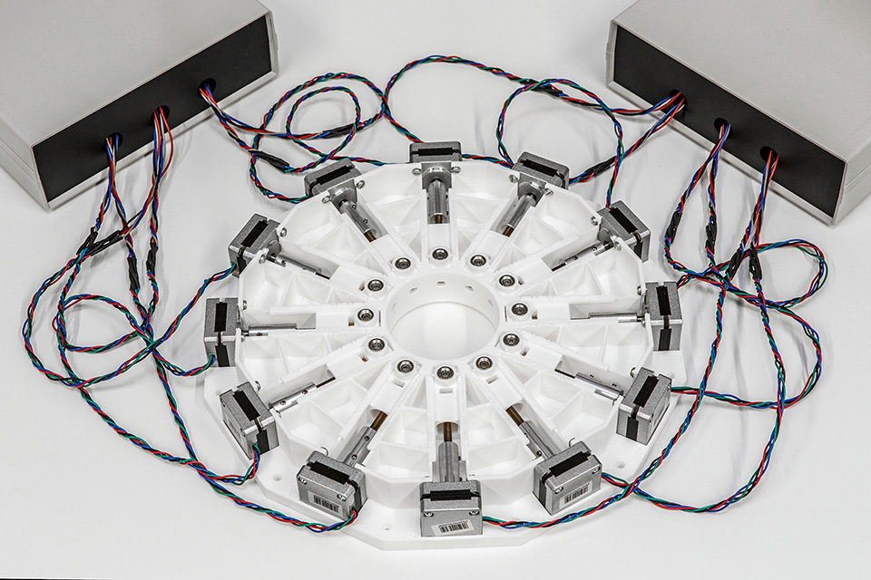
To measure the installation space, it was divided into 27 (3 x 3 x 3) cells. These were filled by the research team so that 9 tensile test specimens per orientation were evenly distributed (see Fig. 1). Quasi-static tensile tests were then carried out.
The results were analyzed for position dependence and orientation dependence. For the former analysis, the installation space was divided into levels according to the 3 x 3 x 3 matrix. For each plane, the 9 positions were averaged, resulting in a comparison value composed of three X, three Y and three Z results.
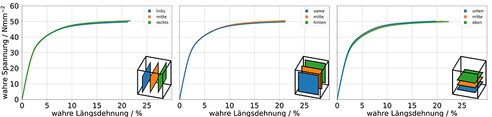
The compared planes are: left-center-right, front-center-back, and bottom-center-top (see Figure 2). For the orientation dependence analysis, all nine samples per orientation were averaged (see Figure 3).
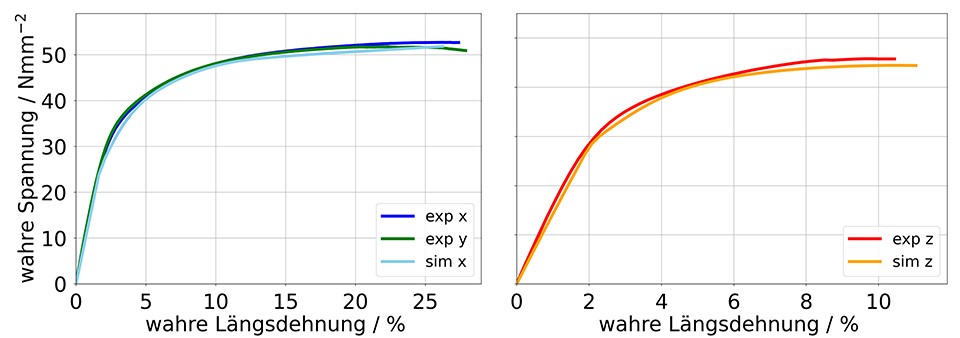
Figure 2 shows the comparative stress-strain curves of the averaged values per plane. There seems to be no position dependence for Young's modulus, tensile strength and elongation at break.
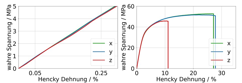
Within the linear-elastic material limits, the Young's modulus is at a comparable level for all specimens. This can be taken from Fig. 3 on the left. If the entire course of the tensile test is considered, strong differences between the compression plane (X and Y orientation) and the build-up direction (Z orientation) are recognized for the plastic range. The elongations at break for X and Y specimens hardly differ, but are almost three times higher than those of the Z specimens (see Fig. 3 right).
It is shown that the mechanical properties of the specimens produced by the SLS process are strongly dependent on the orientation during compression in the build space. It could be shown that there is no position dependence. Based on the experimental investigations, isotropy is assumed in the x-y plane.
A concept for material modeling in the FE program ANSYS was derived from the presented test results. For this purpose, an orthotropic approach was parameterized, which is based on a linear-elastic initial deformation. A Hill yield surface describes the transition into the plastic region, which is modeled with a non-linear strain hardening curve. The compression direction is related to the mesh of the FE simulation via local material coordinate systems.
As can be seen in Fig. 4, the structural simulation adequately reproduces the real material behavior. The procedure was validated on the basis of component samples.
The results presented were generated in connection with IGF project 21105 N of the Forschungsgesellschaft Kunststoffe e. V., Haardring 100 in 64295 Darmstadt, Germany, entitled "Phenomenological strategies for the consideration of process-specific material properties in the simulative design of additively manufactured plastic components". It was funded through the German Federation of Industrial Research Associations (AiF) as part of the Program for the Promotion of Industrial Community Funding and Development (IGF) by the German Federal Ministry for Economic Affairs and Energy based on a resolution of the German Bundestag.
We would like to express our gratitude for this funding, as well as to the Forschungsgesellschaft Kunststoffe e. V. and the representatives of the committee accompanying the project.
»As Managing Director, I am pleased to be involved in current research. In direct exchange, we discuss issues relevant to everyday life and provide printing time, for example, so we also receive additional information about our own printers.«
Felix Wendt, Managing Director Fiberthree GmbH
As part of the AddiSim project, Andreas Grimm's engineering research project was carried out in cooperation with the Institut für Kunststofftechnik Darmstadt ikd. In the project, the approaches for FEM simulations of components from the SLS printer were investigated and the causes of the anisotropic behavior of the components were researched and explained.
The procedure and the results are summarized in a poster: